
Keeping Cool: Thermal Management Basics for High-Density Motor Controllers
If you’re experienced designing, building, or working with motor controllers, or even electronics in general, the importance of keeping temperature under control shouldn’t come as a surprise. For those of you without that experience, let me walk you through why it does matter. Every electronic component has a rated maximum temperature that cannot be exceeded in operation for the component to continue to function as designed. Plus, some components, notably GaNFETs (Gallium Nitride Field Effect Transistor), exhibit worsening performance at higher temperatures. Therefore, there is an upper limit on how hot the components you are working with can get.
Under that thermal limit there are considerations around reliability as well. For example, electrolytic capacitor’s rated lifetime doubles with every 10-degree Celsius reduction in operating temperature. Now, component temperature is not an independent property, instead, it is a result of the ambient temperature surrounding the piece of electronics in question, the thermal resistance to ambient, often given in degrees Celsius per watt, and how much heat a component is producing. As a designer, you can control both the thermal resistance and the heat generation of a component. But, in a motor controller, you generally want to push the upper limits of how much heat is produced by a component to maximize power density and performance. So, the critical value is the thermal resistance to ambient and minimizing that to extract the most motor controller performance.
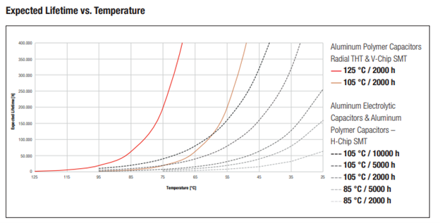
Capacitor temperature vs lifetime, via Wurth
Any motor controller has multiple sources of heat that all need to be considered when looking at the design of its heatsinking. In an approximately descending order from most to least heat generation, the typical components are:
Switching devices, whether those are silicon MOSFETs or IGBTs, silicon carbide MOSFETs or IGBTs, or gallium nitride FETs
Heat generated by conduction (I^2*R) losses, switching losses, reverse conduction losses, gate losses
Capacitors, whether electrolytic, film, or ceramic
Heat generated by the ripple current over the equivalent series resistance of the capacitor (I^2*Req)
Typically low for ceramic capacitors, higher for film and electrolytic
PCB (printed circuit board) traces carrying high currents
Heat generated by I^2*R in these traces, a common design approach for carrying moderate currents (<200 A) in small motor controllers
Inline phase or DC current sensing using shunts
Similar to the PCB traces, generating heat through dissipation in the controlled resistance of the shunt
High current bussing, connections in and out of the controller
An alternative to carrying current in the PCB is to carry current in external busbars that generate heat through resistive losses
Also, any design needs a way to make a connection to the battery pack and motor phase cables, and at these connection points resistive losses exist
Other minor, miscellaneous components
Microcontrollers, LDOs (low-dropout regulator), other power supplies all generate some amount of heat, though typically small and negligible relative to the high current components
Efficient design and selection of these components is a critical factor as well because reducing the amount of heat generated in the first place can reduce the complexity or cost of the heat sinking. However, you’ll have to wait for a later article for that or look back at our discussion of why we design motor controllers with GaN semiconductors for information on this topic.
With that background on where the heat is being generated and why getting it out is important let’s dive in to dissipating it. Unfortunately, this isn’t a topic with one straightforward or right answer as every motor controller design has form factor, electrical architecture, cost, manufacturability, service, etc. requirements that must be simultaneously met. What is possible is to talk about some general best practices and some techniques commonly used in industry today.
As I mentioned earlier, one main goal is to reduce the thermal resistance between the switching device (MOSFET, GaNFET, etc.) and ambient. What might come to mind is directly connecting that device to a metal heatsink to take advantage of either aluminum or copper’s excellent thermal conductivity. There are a few catches though. Typically, the exposed metal pad on a switching device will be electrically connected to the source (high side) of the switch. In a 3-phase, half-bridge motor controller these being directly tied to the heatsink would cause a short circuit on the DC connection from the battery pack. This is unacceptable both functionally and for safety. So, any heatsinking approach must ensure that proper isolation is maintained based on the operating voltage and circuit design of the controller. In practice, this is done in several ways. One approach is to select a switch that has a source pad that gets attached to the PCB, referred to as a bottom-side cooled (BSC) package. This uses the PCB to spread heat with its copper layers and insulate the device with its FR4/epoxy layers. An alternative is the use of a top-side cooled (TSC) package and an insulating but thermally conductive (relatively) thermal interface material. This thermal interface material is a polymer filled with small beads of ceramic that help add thermal conductivity. Another option is to use a dedicated, highly insulating but thin material such as polyimide to allow for a conductive thermal interface material instead of an insulating one.
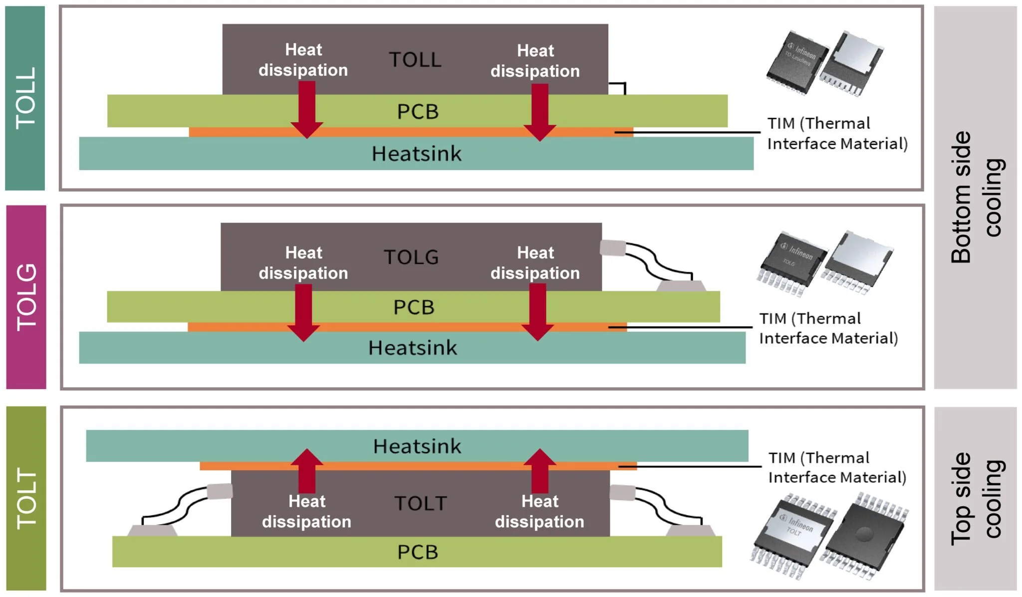
Comparing semiconductor packages, top-side cooled vs bottom-side cooled.
Thermal interface materials often play another role in allowing manufacturing variation and accounting for the roughness of even well machined metal surfaces. These materials are soft and compliant, accounting for both tolerances between your heatsink and the components that need cooling. Generally, controlling the tolerance between the heatsink and the switching device goes a long way, as while these materials are reasonably thermally conductive (3-9 W/m-K), they are two orders of magnitude less thermally conductive than aluminum or copper. Minimizing the height of these materials goes farther than using a higher performance material.
The heatsink itself also plays a major role. Choosing between liquid (water, coolant) or air cooling sets how much heat can be extracted in a given area. Liquid cooling is able to remove significantly more heat per unit area (W/m^2) due to its higher thermal conductivity because of its density. It doesn’t come free though, requiring a pump, seals, tubing, and a radiator to still reject the heat to the ambient air. Air cooling is simpler, and is the typical choice for lower cost, lower power motor controllers where the loss in power density doesn’t lead to an impractically large controller. For either heatsink type, increasing surface area using fins helps transfer the heat out. One other piece of the puzzle in the heatsink is heat spreading. As semiconductor packages become more current-dense, they concentrate their heating further. To improve overall thermal performance, this heat ends up needing to be spread out using advanced thermal technologies with higher effective thermal conductivity than base metals. This is similar to what is seen in computer hardware with heatpipes and vapour chambers.
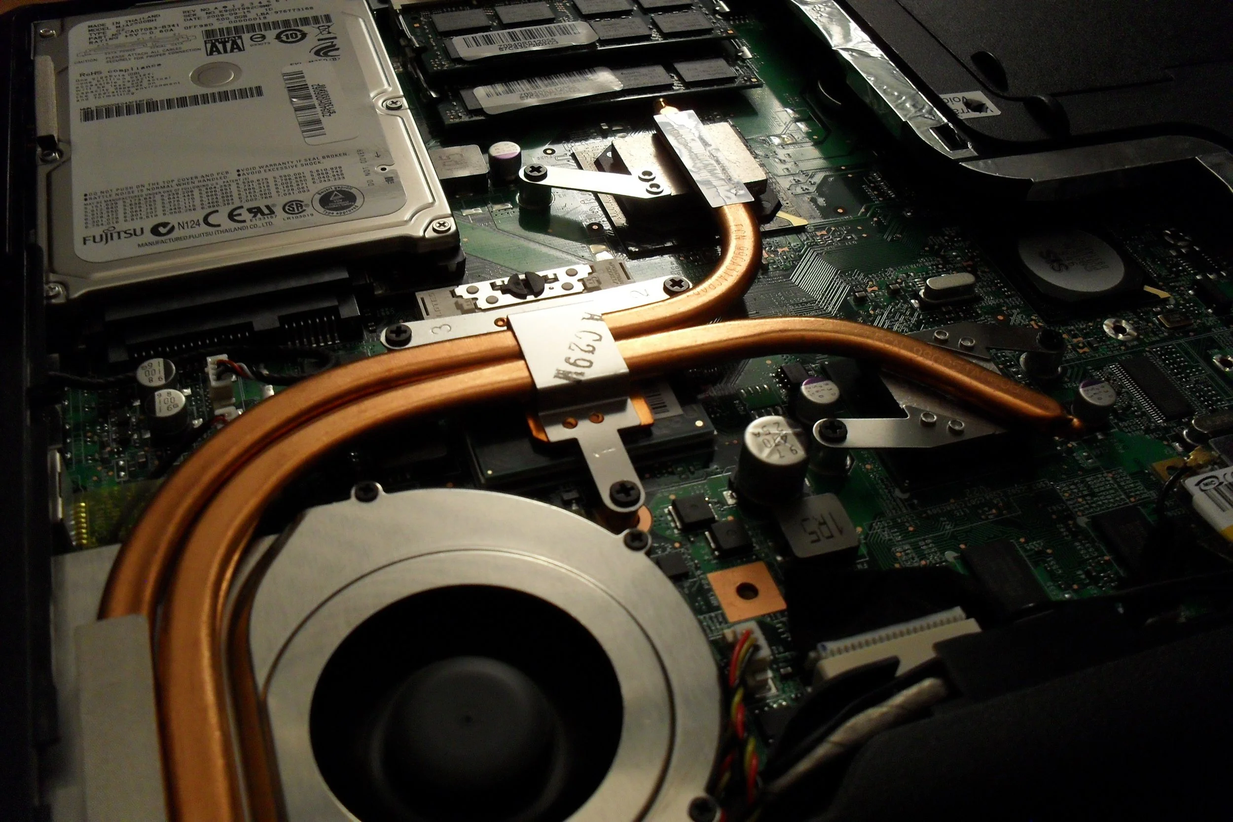
Heatpipes cooling a laptop: By Kristoferb at English Wikipedia, CC BY-SA 3.0, https://commons.wikimedia.org/w/index.php?curid=13144188
In industry, many companies have developed innovative solutions to solve their unique thermal challenges to try and maximize their products performance. One example of this is the innovative approach offered by ST for their STPAK SiC MOSFETs. These use a specifically developed SiC MOSFET that has a thin silver layer on the bottom of the device, which is directly sintered using silver paste to the heatsink. You can learn more and see a cross-section of that here: https://www.st.com/resource/en/application_note/an6280-guideline-and-mounting-instruction-for-stmicroelectronics-stpak-sintering-process--stmicroelectronics.pdf
This approach minimizes the thermal resistance to the water-cooling channel by avoiding the need for any thermal interface material, just relying on a thin insulating layer inside the semiconductor package, similar to what I discussed about using a dedicated insulator earlier in this article.
Now, this is not a comprehensive overview of how to address this challenge, but I hope it’s clear that there are a large number of solutions and considerations when it comes to designing for thermal management. Here at Boron Energy, we’ve spent a lot of time thinking and testing solutions for this problem. How to effectively cool GaN semiconductors in particular has been a huge focus of ours. We’ve built this into our own controllers and are always ready to bring this knowledge to bear on your controller challenges. If you’re having thermal issues with a motor controller, or want a custom solution that avoids these problems entirely, contact me at cole@boronenergy.co to see how we can help.