
Beyond Volts and Amps: How to Choose a Light Mobility Motor Controller
Motor controller selection is an extremely broad topic, ranging from what’s driving your washing machine motor to what’s driving the Tesla Semi. To avoid this being a textbook-length article, there needs to be some bounds put in place. This article will be focused on motor controllers for light mobility; think of small motorcycles, mopeds, and electric dirtbikes. I’m also assuming that the rest of the vehicle is already designed with a motor and battery pack already selected. If you’re designing a vehicle from the ground up, these same points will still apply but will happen iteratively and in parallel with the other architecture decisions. I’ve intentionally led with some lesser-considered factors in the list below, alongside some real examples of matching a controller and motor datasheet:
Motor Compatibility
Motor position sensing compatibility can make or break the selection of a controller. Typically, motors for the light mobility market use hall sensors for sensing their rotor position (where the rotating part of the motor is relative to the stationary part of the motor). However, some use a resolver or encoder instead. All these different sensors require different interface support on the controller. There is a way to side-step these sensing options though, if your chosen controller has a sensorless option, it can sense the rotor position using the voltage and current from the motor only, once the motor has started turning. A way to bridge the startup gap is with high-frequency injection. To do this, the controller adds additional, high-frequency currents to the motor to sense its position even at zero speed.

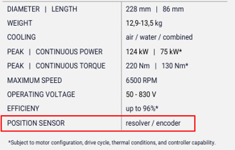
Looking at a motor controller on the left, matched and supporting the motor’s position sensor on the right
Motors also vary in their degree of saliency (how much torque is produced by the motor permanent magnets vs how much is produced through the difference in Q and D axis inductance). This is typically found on a datasheet as a large relative value of Lq – Ld as compared to Lq individually. Highly salient motors perform best when a motor controller can use a MTPA (maximum torque per amp) algorithm to adjust how it drives the motor dynamically. The MTPA algorithm can place the appropriate currents on the Q and D axes to maximize performance. Not all controllers are able to do this, and looking out for this feature can be important.
Mechanical Integration
Mechanical integration (mounting features, size, cooling requirements, sealing, electrical connections) plays a major role in selecting a controller once all the other criteria are met (motor and vehicle compatibility, current and voltage handling). A smaller controller will typically be easier to package, but it’s important to check that its smaller size doesn’t drive a need for better cooling. As the power density of a controller increases, the area of the required heatsink for the same velocity of airflow needs to increase to reach the same level of convective heat transfer.
Another mechanical feature to consider is the IP rating of a controller. If you’re building a dirtbike where you expect your customers to drive through puddles, drop the bike on sand dunes, and end the day by pressure washing all that dirt off, having an IP69K rated controller gives the confidence that the vehicle will be reliable over time.

This chosen motor controller delivers when it comes to ingress protection
It’s also important to look at the choice of electrical connectors and their location on the controller. Are the signal connectors common with the other types being used on your vehicle, keeping crimps the same? Are they located such that they are easy to install on the assembly line, or remove for service? Do the high current connections have good access to drive the bolts if they are fastened? Are the high current cable runs required short to minimize cost?
Software
It’s worth remembering that you’ll likely spend more time interacting with the programming or tuning software of whatever motor controller you select than you will the hardware itself. Software that is poorly documented in the GUI, doesn’t positively confirm configuration changes, doesn’t have data viewing functionality, and doesn’t provide clear error messages can lead to countless wasted hours trying to debug and configure a controller. It’s worth having a controller supplier demonstrate their software and let you demo it before committing.
For more advanced users, it becomes a matter of how much you can control. A controller vendor may not totally understand your specific needs and accordingly not give you the flexibility you need to customize your tuning.
Top-Line Specs
The simplest choice is picking a controller rated to the voltage your battery pack operates at. Controllers often list a nominal voltage they are designed for (e.g. 48V, 72V, 96V) or, sometimes, the number of NMC cells in series they are designed for (e.g. 14S, 20S, 28S). However, it’s also a best practice to check the maximum voltage the controller is rated for, and how that compares to the 100% SoC voltage of your battery pack. Non-standard cell maximum voltages could push the voltage over the controller rated voltage, which is set based on the limits of the internal components (capacitors, MOSFETs).
Another top-line spec is phase current capability. This value is usually listed as a peak (possible for a short period of time) and a continuous (capable indefinitely, given the listed cooling conditions) current. These are listed as either an RMS value or a peak (maximum value of the AC current). This value is important because most of the heating in the controller, and thus its performance limits are set by how much phase current is flowing. The active phase current also determines how much torque the motor is producing. For selecting a controller, the rated continuous and peak current for the motor should be listed on the datasheet. The controller can be chosen to match those values, though often a motor can handle a peak phase current for longer than the controller, due to a larger heat capacity.
You might assume that battery current and phase current are directly connected then, as both are current values on the datasheet for a controller. However, the motor controller transforms the input DC battery voltage and current into a modulated, 3-phase AC voltage and current where the voltage may be significantly lower than the DC voltage and the current significantly higher, when the motor is running at a high torque and low speed. You can think of the motor controller as being power balanced across the two sides – Power In from the battery – losses in the inverter = power out to the motor. That said, the motor controller should be chosen such that it can draw enough current from the battery to hit your target vehicle power.


This controller and motor are well paired, generally. It’s worth noting that the controller lists continuous current in A, not Arms - hopefully a typo. It also can only deliver it’s peak current for 30 seconds, falling short of the motor’s 2 minute peak current rating.
Vehicle Compatibility
If, as I assumed to start this article, you’ve selected the other components on your vehicle first (throttle, display, BMS, etc.), the motor controller necessarily needs to support those other components. By that I mean how they communicate, whether that’s over CAN or UART, and what the commands on the specific bus are. For example, a throttle could be implemented as simply a directly sensed voltage signal that gets measured by the motor controller. Or, it could be a signal that is routed over CAN from the throttle to a vehicle control unit, then sent on via CAN to the motor controller. Battery management systems (BMS) can range in their sophistication, sometimes just broadcasting state of charge as a voltage value, but in other scenarios can share information about their state of charge, allowable charge and discharge current, temperatures, and state of health in real time. These are just two examples of the variation in communication that exists on real vehicles.
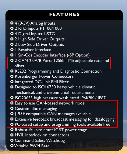
Solid software and communication support on this motor controller.
One other feature of a controller that can stand out is whether it supports regen. Most controllers today do have regen included, allowing the controller to apply braking currents to the motor, taking energy out of the vehicle’s motion to charge the battery. This helps extend the vehicle’s range without any additional hardware.
Summary
Selecting the right motor controller requires balancing several trade-offs, and that’s even ignoring typical engineering ones like cost, functional safety, and reliability, or business ones like customer support. Here at Boron Energy, we strive to meet the balance of these needs and build great, well-supported motor controllers. Plus, if there isn’t an off-the-shelf fit, we can customize our existing controllers or design a fully custom controller that solves your problems. If that sounds like you, you can reach me at cole@boronenergy.co.